Logic Circuit Diagram Designer
Web circuit diagrams are used for the design (circuit design), construction (such as pcb layout), and maintenance of electrical and electronic equipment. Web design a neat, clear and professional circuit diagram for free. Transfer the truth table into a. Welcome to digikey's free online schematic and diagramming tool.
Logic Gates with Diagram Circuit AHIRLABS
Logic Gate Circuit Diagram Examples / Logic Gates / The problem of Electrical the circuit’s logic diagram of a (2bit binary to decimal Draw a Logic Circuit in CircuiTikZ TikZBlog
Web Build And Simulate Circuits Right In Your Browser.
Create your circuit diagram now available for windows, mac and linux. Circuit diagrams are the perfect way to show the design of the circuit. Web design of the circuit:
Analog & Digital Circuit Simulations In Seconds.
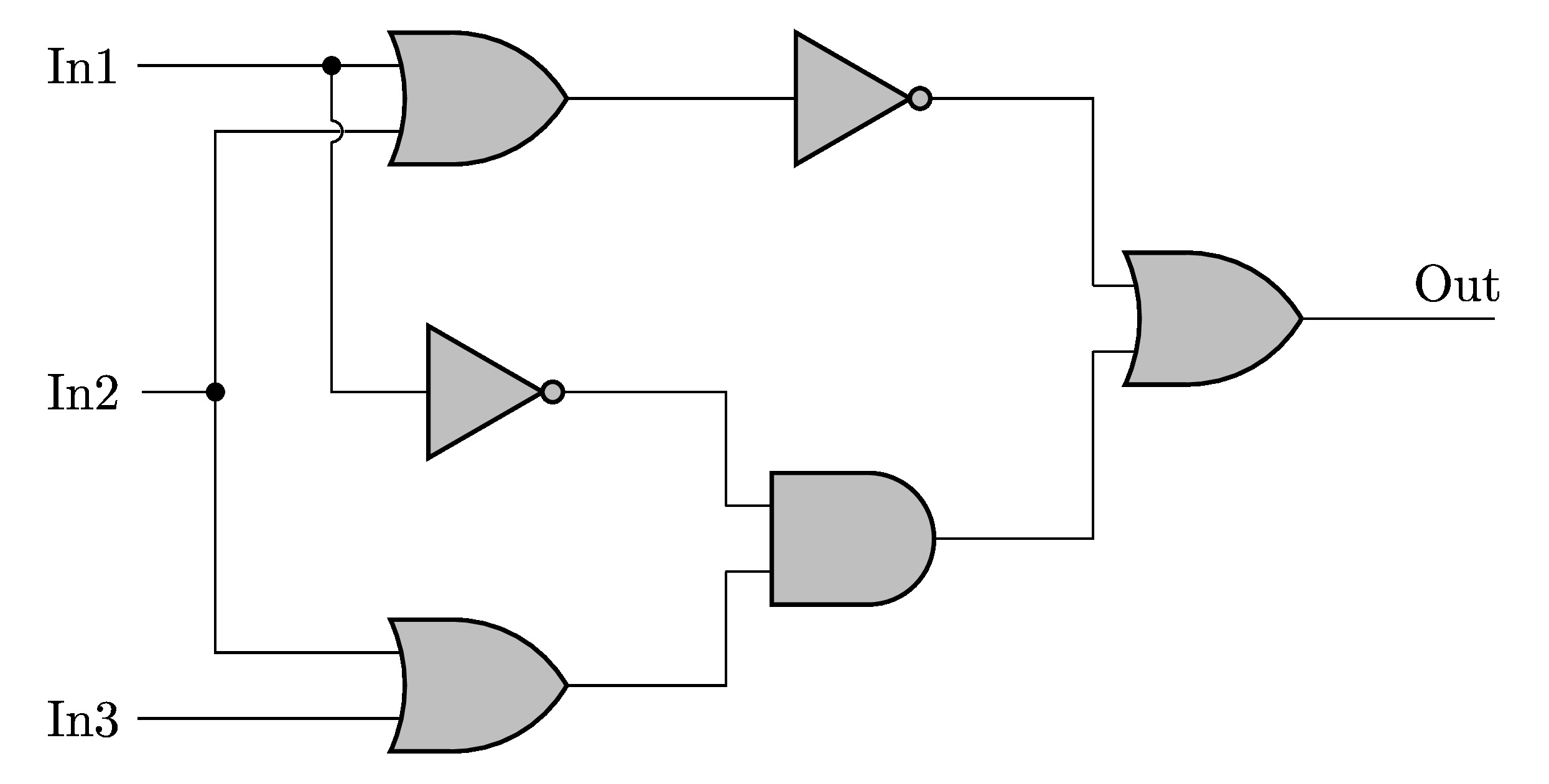
While understanding the symbols and their. Web a logic diagram shows how multiple gates are connected to form a digital circuit that is further expected to perform a particular task. Web the following is a systematic procedure to design a logic circuit:
Web How To Create A Logic Circuit Diagram Add Symbols.
Web this product is a simulator for logic circuits, allowing the student to better visualize and understand how a logic circuit works, by enabling him to build whatever. Create the design by dragging the symbols from the stencil and dropping them onto the diagram surface at. We call that a logic circuit.
It's Not Difficult At All.
The circuit diagrams are always true to nature. Hence, they show the picture of. Web from detailed schematic drawings to graphical diagrams and flow charts.
Web Google Classroom Computers Often Chain Logic Gates Together, By Taking The Output From One Gate And Using It As The Input To Another Gate.